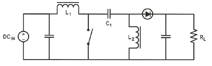
Sepic Converter Inductors
Application Features
The SEPIC converter allows the output voltage to be greater than, less than, or equal to a required nominal voltage.
- The output voltage polarity is the same as the input voltage thus allowing a common ground.
- DC isolation is provided by a capacitor.
- The two inductors can be wound on the same core.
- Efficiency is significantly higher than most other DC-DC converters.
Requirements
The SEPIC converter works best in a continuous-conduction mode. This is when the current through L1 never falls to zero. This is similar to the familiar DC choke input filter where the inductive reactance minimum is 2/3 of the minimum load resistance. One simple check is to make the nominal value equal to the load resistance to allow for a ± tolerance of the inductors and roll-off with DC.
- The voltage across capacitor C1 can reverse every cycle, so a non-polarized capacitors should be used for C1. They should also have a low Equivalent Series Resistance (ESR).
- The diode’s switching time needs to be fast in order not to generate high voltage spikes across the inductors.
- The inductor windings can be on the same core. Therefore, standard DC chokes like MCE’s DL series with 2, 4, or 6 windings can be split. The average current through L2 is the same as the average load current.
Reference
www.planetanalog.com