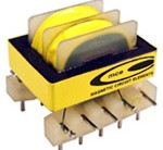
Flybacks are very popular since they can accommodate a wide input voltage range. However, they are limited to moderate output voltages. Flyback designs are not suitable for high step-up ratios because distributive capacitance reflected from the secondary back into the primary can be very high. In addition, flyback designs are not suitable for very low step-down ratios due to poor coupling of few turns.
High efficiency power conversion using flyback transformers can be achieved. One important requirement is to minimize the primary leakage inductance. When the primary leakage inductance is kept at a minimum the losses in the snubber circuit are minimized. Decreased snubber circuit losses result in higher efficiency power conversion through very low primary leakage inductance. It is important to note that measuring short circuit inductance is a relative indication of primary leakage inductance; however, it is not necessarily the actual leakage value except under special circumstances.
Pin out assignments on PC bobbins are important to permit good coupling, and also to meet UL safety specifications and therefore should always be negotiated with the transformer designer. This is also important for the core configuration chosen.
Flybacks can save space when designed at high frequencies. However, there are many practical issues such as UL specifications that can have a significant effect on size, especially on very small parts.
Multiple secondary windings in parallel are frequently needed to carry high currents and can be terminated on small PC pins. This does provide other options on standard parts such as separate isolated windings or center tapped windings.
[[Flyback_transformer | See Wikipedia Article ]]The MCE standard flyback transformers are normally designed for discontinuous mode because it is necessary to know the minimum current for a continuous mode. Modified standard parts can be provided when this is desired when the minimum current can be furnished.
The EE17GT7 is provided for those that desire several different low voltages ( 5v or 3.3v ) that can be obtained with Point Of Load (POL) simple inductor buck regulators and that do not require isolation.

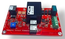
An evaluation board, DB2320 is also offered for a 28 to 3.3 volt, 6 amp power supply.
| EEGT rev-A Spec-Sheet | 81.1 KB | EJ50HT Spec-Sheet | 65.3 KB | O-1856T2 Spec-Sheet | 21.6 KB | O-1973T15 Spec-Sheet | 137.8 KB | O-1975T6 Spec-Sheet | 137.8 KB | O-2232T1 Spec-Sheet | 21.2 KB | OE13GT rev-B Spec-Sheet | 71.4 KB |